Development of the JLD dyke stabiliser
In 2013, JLD Contracting BV entered into collaboration with Antea Group and Wiertsema & Partners. With the support of these partners, JLD Contracting entered into a unique partnership with Waterschap Rivierenland to turn the concept of the JLD dyke stabiliser into an accepted system within the High Water Protection Programme (HWPP). This innovative technique to improve dykes, which aims particularly to improve inward stability, is a design based on an idea patented by Mr Jos F. Karsten, director/owner of JLD Contracting BV, with its registered office in Edam.
Together with the partners, an experimental design was set up with Deltares, who assists the development on behalf of Waterschap Rivierenland, the contracting authority. After extensive soil investigations, multiple calculations and many meetings, the tests were initiated at a location made available by the municipality of Purmerend. One of the basic ideas is that what has already been investigated and deemed useable need not be investigated again. This data, which is often available for the market, will be used optimally within this development. Below we provide insight into the main elements of the system’s operation and the test procedure method.
Current development status of the JLD dyke stabiliser
The preparation phase is ready and the project team has started the first tests. All of the parties involved jointly with Deltares are working on this project with full commitment. This has led to the test design, which allows us to extract all information required to fill the remaining knowledge gaps.
In the field, the top layer of the test dyke is excavated and the dyke body is installed on top of this, reaching a height of approximately 1.40 m. In addition, various monitoring systems are installed, including piezometers and measurement posts. The subsoil and clay for the dyke body are analysed by means of compression tests, single stage triaxial tests and DSS tests. The Atterberg limits as well as the volumetric weight/water content of the dyke material are also determined.
The tests are modelled in Plaxis 2D/3D to monitor the extent to which the stabilisers theoretically contribute to the dyke body’s macro stability and how the test can be best carried out so that the desired slip circle is achieved. On the right: an illustration of the work on the stability analysis for the container test/test dyke.
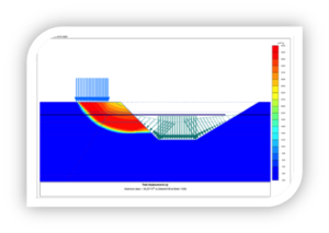
Figure 1: Container test stability analyse
Expected Planning
- The interaction tests are virtually finished;
- As of April 2015: having the container tests give way;
- From May through July 2015: elaboration of the results;
- End of 2015: achieving acceptance of the JLD dyke stabiliser.
Operation of the JLD dyke stabiliser system
Objective: Improve inward stability
The JLD dyke stabiliser consists of four parts:
| JLD Anchor | Transfers tensile force to the subsoil |
| LDE (fin) | Element transfers transverse force to the soil |
| Draw rod | Transfers transverse force via LDE to JLD anchor/LDE |
| LDP (head plate) | Links surface to JLD dyke stabiliser |
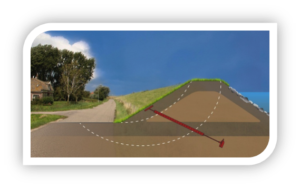
Figure 2: Operation of the JLD dyke stabiliser system
Testing the JLD dyke stabiliser system
After working out the theoretical substantiation, it is important to carry out a practical test. These tests serve to examine whether the JLD dyke stabiliser operates as assumed in the theoretical substantiation and as appears from the various models. The tests are divided into two parts: the interaction tests and the container tests.
Main objectives of the interaction tests:
- Determination of the force that a JLD anchor placed in the deep soil (pleistocene, holocene sand layer) can accommodate;
- Determination of the frictional force that an LDE element placed in cohesive layers can accommodate;
- Determination of the force of that the combination of a JLD anchor and an LDE placed in the soil can accommodate.
Main objective of the container tests:
- Optimisation of design method of the JLD dyke stabiliser;
- The centre-to-centre distance of the JLD dyke stabilisers can be optimised;
- Differences between an LDE from a single part or from multiple parts can be investigated;
- Determination of the transverse force absorbed by an LDE placed in the soil.
- Determination of the forces that the JLD dyke stabiliser can accommodate in a situation that most closely approximates the eventual application area of the JLD dyke stabiliser;
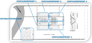
Figure 3: Test design
Development Costs
The entire development is made possible by the new scheme provided by the HWPP.
Within this new scheme, innovative projects are 100%-funded (instead of 90%) and the risks associated with the innovation’s eventual failure are borne by the programme. Naturally, JLD Contracting takes responsibility within this range of risks – this is primarily for execution and materials. The energy, commitment and speed with which the project is conducted prove that the new HWBP approach offers many opportunities that allow SMEs to bring great ideas to life.
In HWBP’s annual Scan, the JLD dyke stabiliser is seen as particularly promising.
JLD Contracting bv and its partners are extremely enthusiastic about the success of this development. The preliminary results of the tests are very satisfying.